
Model B Instructions
Frequency Instrument Operation Manual
MODEL B-27 Version 3.5d 110/115 VAC ONLY
(FOR EXPERIMENTAL PURPOSES ONLY)
Version 3.5d
This machine is very stable for analog. TM drift at 10,000 hz is less than 1 hz. However, it does possess the normal drift in frequency output, as it should be. Usually, these systems stabilize further after about 2 years of normal use.
The counter will only try to count up to about 13,500 before it starts to zero out or locks up. This is normal. If the output appears erratic, it is not. This indicates that the frequency is set outside the operating range for the digital DISPLAY. Nothing more.
The frequency will usually tend to drift downwards as the elements heat up. It is sometimes a little tricky to adjust through a specific range manually, but the idea is to use the natural drift as the modulator by leaving the adjustment set slightly above the exact number, and allowing a drift-through. It will be more noticeable at higher frequency settings.
The tuning acuity is not limited to the operating range of the built-in counter, and though a 25 hertz reading will be correct, it will take several turns at least to advance to 26 hertz. Therefore, with an external counter capable of acuity of .0001, you can tune the instrument to 25.001 and so on. The FINE adjustment is at least this precise in range A.
Although it does lose some acuity at higher settings, it is capable of extremely fine frequency increments in all ranges, even if they cannot stay completely stable. If it ever becomes necessary to use specific frequencies as per a special protocol that requires very high accuracy, this machine will likely be able to achieve it.
Please carefully read the cautions section of the Applications Guide before attempting to use the Model B device.
Save all original packaging, in case the device has been damaged in shipping. After removing the instrument from the packing cases, do a ROLL TEST.
Hold the machine in both hands and turn it over several times. If there sounds like anything larger than a grain of sand is loose inside, the machine may have been damaged in shipping. Do not accept. Return in the original cases via UPS, as damaged, for insurance purposes. If there is nothing loose inside, the machine is probably okay.
Stand the machine up on a clean, level surface so it rests on the four grey plastic feet on the bottom side. Insert the power cord into the unit. You must extend the prop-stand at the back of the instrument in order to lay it down. This prevents the air intake from being blocked.
Tum all 4 knobs all the way to the left. (Top of the knob towards you) counter-clockwise. This is downward. The range switch has 4 positions A, B, C, and D. In this instance, it is put in the A position. (They are not marked on the machine.)
Find the red POWER switch, and switch it on. The power switch should glow bright red. (It does not light up for 220. Though the switch is rated for 250, the neon bulb is not.) Listen for the faint hum of the cooling fan. The COUNTER, will momentarily display an error code, and then read:
R 3
Or something close to that. This is the normal starting point to familiarize yourself with the behavior of the instrument. This COUNTER has a TOTALIZING feature:
- Is not used in this application.
- The COUNTER is normally used on R mode. (Real time)
- Press the SEL button to change to totalizing, RST to reset the display. Press the SEL again to return to R mode.
Output Check
The vernier dial is the front-most control on the lower left. Marked AMPLITUDE. It is more than a simple knob, it is a calibrated dial. The lever on the side of the dial slides to the right to lock the control. Slide to the left to unlock.
To check the output, an accurate oscilloscope or other tester will be needed. Set the machine on range B, and turn the AMPLITUDE knob all the way up clockwise. On this machine, maximum should be about 80 volts.
Troubleshooting
NO OUTPUT
Leads with broken wires are the most common problem. Check one set against another.
- If new leads do not correct the problem, test the Range switch subjectively. Hold both electrode pads, turn up the amplitude until you can feel the output well enough. Turn the switch normally from A up to D, and back down again several times. If any of the channels are dead, or intermittent, you will feel the voltage drop to nothing for a few moments. This indicates a fault in the selector switch.
- If the counter does not display normal characters, but the output seems okay, the counter may be at fault.
- If there is no output, the counter will read zero. This indicates an internal problem.
Handle with care.
Absolutely do not drop! No warranty for mishandling.
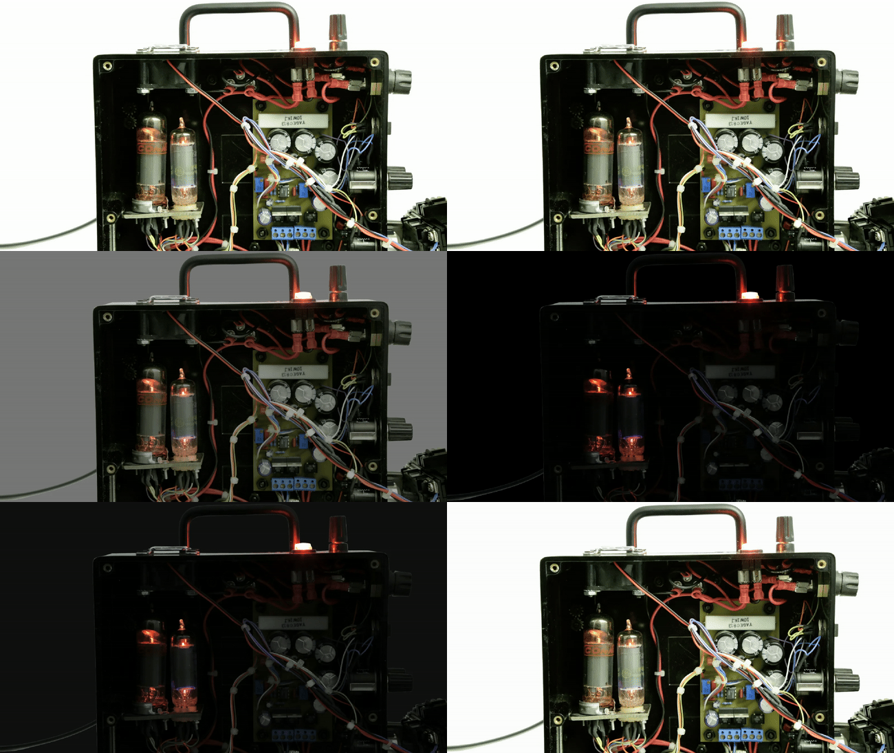
The most common hazard to the machine, and cause of breakage occurs when the user forgets that electrode pads are still attached and tries to stand or walk away without unplugging or detaching first. The lead wires become taught, pulling the machine over, off of a table, onto the floor. This may damage the tubes. The instrument may have been hit hard enough to knock the tubes out of their sockets. Nothing else might be wrong with the device. If the case is cracked, or it fails the ROLL TEST, seek an electronics specialist for repair.
Warning: On Warmup
The machine will build up about 1 volt of excess charge every 5 minutes of non-operational circuit open condition during warm-up. Simply unplug and re-insert the output plug to discharge this build-up, or make use of a grounded probe inserted into the top of the binding post, this will accept common banana plug connections.
BASIC OPERATING INSTRUCTIONS
Depending on the application of the frequency instrument and the electric power at the location in which it is used, the purchaser is strongly cautioned to CAREFULLY read this section and decide if the unit is going to need an AUXILIARY GROUND WIRE. This must be determined again any time the unit is used in a new location, even when it is moved from one room to another in the same building.
For applications in the laboratory, home electronics projects, or other uses where greater precision is required, or when used with an amplifying device, an auxiliary ground wire is highly recommended. (see 9. & 10.)
1) FOR EXPERIMENT ONLY
The frequency instrument is designed for experimental purposes only. There are no medical claims made by the manufacturers. The PURCHASER assumes all liability for damages, and any other personal injury incurred by any person allowed to operate this device.
2) METER
No meter is installed on this device.
3) COUNTER
The backlit LCD counter will count the precise frequency to the nearest whole number and display a new count in intervals of 0.1 seconds. When the counter reads 3, the number of output pulses per second will be three hertz. When the counter reads 2000, the number of pulses per second will be two thousand.
The output SIGNAL is analog. The displays are digital. This display is not able to read fractions of hertz. Output is capable of approx. .00001 of a hertz in range A. For greater tuning accuracy, use an external, high accuracy counter.
4) POWER
Should you find that when you plug in the device, you can hear the cooling fan running, but the red light is out or is very dim, you will need an auxiliary ground wire at that location. If it does not have a good ground it will begin to produce dangerous current spikes.
When the auxiliary ground wire has been added, and the light still does not come on, or is not bright, the device may still be safe to use. (Test output with a separate tester or meter.) This may mean that the electric wiring in that location has reversed polarity. This will not affect the device’s output signal. It will require a 230v down-step to 115v converter of at least 50 watts capacity for applications in countries. other than the U.S…
5) AMPLITUDE
Like any volume control, turn clockwise to increase. The vernier dial should be turned slowly. The lever on the side of the knob, slides to the right to lock the control. This knob will rotate ten (10) times from zero to maximum. It will read 1 at one turn, and up to 10 turns.
6) FREQUENCY
The coarse frequency adjust knob controls the output frequency from minimum to maximum in ten(10) turns. The fine adjust knob is 1O times as precise as the coarse adjust.
It is normal for the frequency to take a few minutes to settle down after the device has been turned on. Let the unit warm up. Variations in frequency are normal. Higher frequencies will generally vary more than the lower ones. Amplitude will affect frequency a smaller overall percentage in C & D Ranges. Frequencies are more stable toward the low end of each Range.
7) RANGE
The range selector is a switch that changes the frequency potential from low (A) to high (D). The total potential of the four ranges combined varies from one unit to another. This average is approximately 0 to 30,000+ cycles per second, to 0 to 40,000+ cycles per second. Each range is overlapping. Range A will produce a maximum frequency that is slightly higher than the lowest frequency of B, and so on...
8) POLARITY
The polarity switch reverses the polarity of the output of all sets of OUTPUT jacks. Many lead sets are NOT marked positive or negative.
To determine which side of either jack or lead is positive or negative, the side of the jack or the lead that produces the signal (live) will always be the positive side. The other side of that lead set is ground. Mark them if they are not marked. Note which position the POLARITY switch is in.
9) POWER CORD
This is a 3 pronged appliance cord like the ones used with computers.
CAUTION: If the device should perform erratically, or respond slowly, it may not be grounded.
If you use an adaptor to make it possible to plug into a two spade household outlet, you must be sure that the adaptor is installed correctly, and the wire or loop that makes the ground circuit is firmly connected. This will not work if the junction box in which the outlet is mounted is not grounded. Do not assume that simply because you have properly installed an adaptor, that the unit is grounded. Many junction boxes are not grounded, or their grounds have deteriorated over time. When in doubt, use the BINDING POST.
10) BINDING POST
The Binding Post is located on the top of the unit and is provided for easy, quick connection to ground, when no grounded outlet is available. It has a cap that unscrews far enough to expose the post itself, but the cap is not intended to come off.
The post is a steel stud, with a small hole bored through it to accept a bare wire. You would then tighten the cap to secure it. You may have to use the ground site that was intended for your house current. This is usually a clamp that holds a heavy solid core wire to a water pipe. They are sometimes soldered directly to the pipe, and they are not always easy to find. Have an electrician add your ground wire to the clamp if that is convenient, but be sure that the contact areas are cleaned and any wire that was already there, is replaced and reclamped carefully.
Another, often easier method of creating a guaranteed ground, is to use the GROUNDING SPADE, not provided. A suitable hole must be bored and tapped to accept a machine screw, 440 is okay for a trowel, larger for a shovel or garden spade. To secure the wire very firmly to the metal of the tool. The blade must not be very rusty or painted.
The advantage to using a spade, is that you can easily remove it, when you move your unit, and it will work in most locations. The disadvantage to using a spade is that your soil must be thoroughly dampened, and if you move your unit around quite a lot, it may be a problem for some people to handle. An alternative to the spade, is to clamp the wire to a water pipe. To do this, you must be absolutely sure that it is a water pipe. No PVC pipe (plastic). (Sounds dumb, but it has to be said: NEVER GROUND TO A GAS PIPE.)
If you are using insulated wire, strip ½ inch at one end. Insert this end into the hole in the binding post, and lock down by tightening the cap.
11) FUSE
The fuse holder is located on the right-hand side, has a quick release cap that is depressed while turning counter clockwise to remove, and clockwise to replace. It holds a 2.5 AMP fuse. Do NOT try to inspect the fuse while the instrument is running.
12) OUTPUT
The two sets of twin output ports (jacks) share the same source. Each port will deliver the total output (about 1/40oth amp) with amplitude at maximum. The full 33 milliamperes will be channeled through one port when only one at a time is used.
13) SURGE PROTECTOR
Adequate surge protection is built into the device. (600 volts) If surges are detected in the output of the unit, check or replace the auxiliary ground wire if you have one.
If excessive electrical surges are common at the location, and a surge protector is used, the output of the device may be interrupted temporarily, while the surge protector is holding back a power surge. Sudden increases in output may result when the surge is over. It is recommended in these cases to use a surge protector that contains a power supply, or uses other means to maintain a constant house current.
14) INTAKE FILTER
The air intake is designed to flow about twice the capacity of the cooling fan. This cooling is essential to the continued life of the instrument. It must not be blocked during operation. The prop-stand on the back of the device and the location of the power cord receptacle tend to prevent this blockage. Should the unit overheat, it will discolor the paper label, indicating that the unit needs an inspection at the factory.
15) WARRANTY
This product was retired in 2004. No machines of this design have been produced since then. A qualified radio/TV repair technician should be capable of performing any replacement of parts that will be required. Vacuum tubes have a life expectancy of about 1O years, and may be replaced easily. [As of this update in 2025, these vacuum tubes have long been obsolete and may be unattainable.] Due to the nature of the product, and the contract under which it is manufactured, there will be no refunds.
16) SPECIFICATIONS
The exact specifications for each instrument are different. The unit is constructed within the correct parameters for the purposes for which it was intended.
There are variables within the make of each component that cause the total output voltage to vary, a small percentage, from one unit to another. The total frequency potential of each unit will also vary. This is because each unit must be adjusted separately. For most, it is not important that range A reaches a few hertz more on one unit than does on another.
Range settings A through D always overlap, allowing the full range of frequencies. Any changes in application parameters that may become available as the result of future research, will most likely be executable with this device.
The device is capable of producing more voltage than is thought to be needed for human or veterinary transcutaneous applications, and can produce frequencies higher than are needed. IT IS THEREFORE DANGEROUS FOR CHILDREN, and must be used at settings appropriate to the impedance of the individual. Maximum output could cause death to some people if used negligently.
The frequency instrument is designed to last for 20 to 30 years or more, and in that time, new things will undoubtedly come to light
The minimum output is set at the factory to about 3 volts. The maximum frequency potential is always set to exceed 20,000 cycles in RANGE D. Any attempt to change internal settings may result in damage to the unit and voids the warranty.
17) HANDLING
- The frequency instrument is a hand constructed electronic appliance that employs electron tubes. There are parts inside that may break if the device is handled roughly.
- As with any piece of home electronics, humidity and water can damage the equipment Do not expose to excessive heat
- Although the unit can be stood up on one end for easy carrying, it is designed to be supported by the folding stand on the bottom of the unit
- NEVER block the cooling fan. To do so may result in the unit overheating, and cause severe damage to internal components. The fan uses a dry bearing, and must not be oiled. If the fan should become noisy, it may need to be checked for small pieces of debris which may become lodged there.
- Do not allow the device to rest on its knobs.
- Do not enclose the unit in any soft carrying case along with containers of liquids.
- To clean the device, wipe with a soft dry cloth. If it becomes very soiled, apply a small amount of household window cleaner, or Endust for Electronics to the cloth to remove dirt and fingerprints. Alcohol or more powerful chemicals will damage the label and other plastic parts.
- Should the power cord become damaged or lost, you can replace it with any (US) computer power cord.
- Specialty leads can be adapted from stereo and microphone cabling for recording sessions to be used with spectral devices such as Model A and related types.
All approved leads, lead extensions, electrode pads and other useful accessories can be found here: https://jwlabs.com/3-rife-accessories/
For help and other product support, reach out to us at [email protected]
To purchase one of our current products, click here, or learn more about them by selecting from our list of Rife Machines in the navigation bar at the top of the page.